
Posted: Jun 17, 2022
In our last blog, we dove into Chapters 27 & 28 of the Metalforming Design Handbook, also known as the “Red Book.” Industry leaders recognize our “Red Book” as the go-to manual for precision metal forming practices. Chapters 27 & 28 taught us about the dimensioning practices for turret press and press brakes. Now, join us as we take a closer look at laser cutting and laser considerations in Chapters 29 & 30!
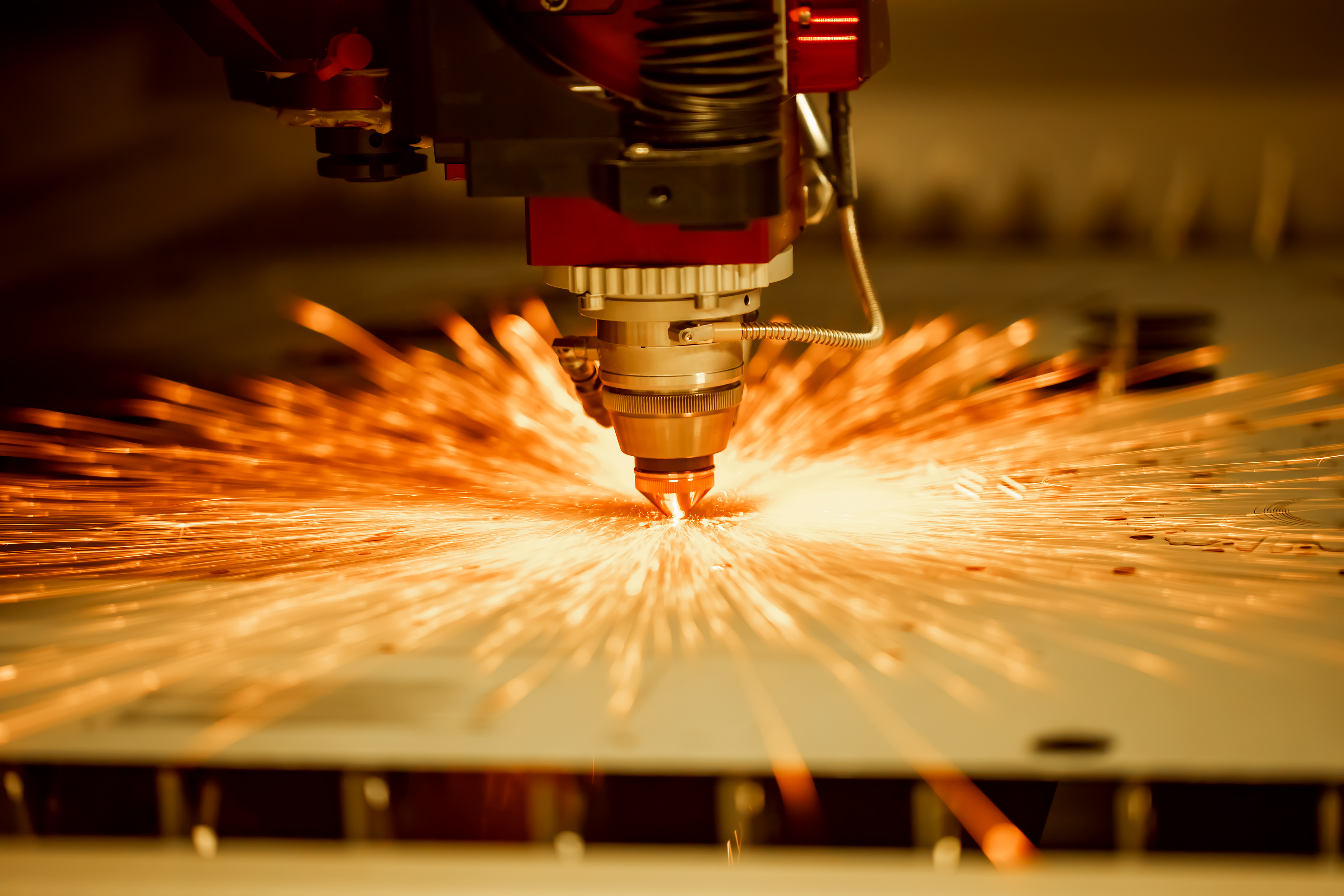
Laser Cutting
Current trends toward just-in-time (JIT) manufacturing, shorter part runs, and limited product life cycles have increased the use of laser cutting machines in production and prototype fabrication. Laser cutters are constantly evolving, as manufacturers find new and innovative ways to apply this basic technology.
Laser Considerations
In addition to production economics, precision, and edge condition, the knowledgeable designer considers these characteristics of laser-produced parts when designing for lasers:
• Localized Hardening. Lasers are cut by melting or vaporizing metal. This can create problems when cutting heat treatable materials as the area around the part will become case hardened.
Laser-cut holes in stainless steel or heat treatable steel alloys which require machining (tapping, countersinking, or reaming) can be particularly troublesome. By the same token, designers can employ this characteristic to their benefit when a product must be case hardened for wear resistance.
• Edge Taper. The laser is most accurate where the coherent light beam enters the workpiece. As the beam penetrates the part, the light scatters creating an edge taper condition similar to but opposite from “breakout” in a sheared or pierced part. (The hole on the side of the workpiece from which the laser beam exits is generally smaller in diameter than the entrance side).
Thus the designer must carefully consider the final use of the part and, in some cases, may have to specify from which side the part should be cut.
• Minimum Through-Feature Size. The cutting laser beam is focused down to approximately 0.010 in. (0.2 mm) and is therefore capable of cutting holes and features with radii approximating 0.030 in. (0.76 mm). The limits applicable to piercing or blanking with a punch and die, such as the relationship between minimum hole size and material thickness, or the minimum distance between features to avoid distortion, does not apply when laser cutting.
• Micro-tab. Holds part in the sheet while processing, generally removed after processing. Can be strategically located so removal is not necessary, resulting in cost savings. The general size of the micro-tab would be .25mm-.5mm.
Since no mechanical force is applied, the width of material remaining between cutout features may be very narrow without distortion occurring during metal removal. A typical application would be tight-spaced venting slots on a visually important surface.
Note: Minimum Features equal to material thickness.
It should also be recognized that the laser, like any other CNC servo-driven machine, accumulates mechanical, thermal, and electro-mechanical tolerances during the production cycle. For economy and quality, critical dimensions should be highlighted and functional dimensions should be detailed in accordance with their function.
Download the Red Book!
If you’re interested in reading the full version of the Metalforming Design Handbook, click the button below.


8401 West 35W Service Drive, Minneapolis, MN 55449-7260 1-800-677-8881
© 2022 Dayton Rogers. All rights reserved