In our last blog, we dove into Chapters 25 & 26 of the Metalforming Design Handbook, also known as the “Red Book.” Industry leaders recognize our “Red Book” as the go-to manual for precision metal forming practices. Chapters 25 & 26taught us about the measurement and limits of burrs and flatness. Now, join us as we take a closer look at the dimensioning practices for turret press and press brakes in Chapters 27 & 28!
Dimensioning Practices for Turret Press
If there is a single area where the designer can accomplish the greatest benefit in reducibility and economy of manufacture, it is perhaps in communicating effectively with the supplier and using appropriate detailing practices on drawings. Following are a few basic guidelines which can make an enormous difference.
First, select a meaningful datum in the body of the part—passing through the hole center, if possible—rather than using an edge or corner of the part. (See #28-Dimensioning Practices for Press Brake). There are several reasons for this suggestion.
It avoids problems of possible misalignment of the part, distortion from clamping, etc. It allows for more precise measurement by avoiding measurements from edges, which may be tapered and therefore dimensionally uncertain. It facilitates accurate inspection and it avoids unnecessary accumulation of tolerances.
Second, on related hole patterns, dimensioning and tolerances should be within this pattern with only one dimension linking to the general datum. Better quality control and function of the product can be expected.
Third, highlight the truly significant dimensions. Critical dimensional relationships can be protected if they are known.
Dimensioning Practices for Press Brake
Practical experience has proven that dimensioning and measuring practices must both be understood and agreed on by all parties to achieve a workable, mutual standard. Formed sheet metal parts present a unique problem in that angular tolerances, as well as the flatness conditions, interact with single plane dimensions because of the flexibility of sheet metal, especially the thinner gauges. To achieve consistent results when measuring formed parts, a standard has to be established on where and how dimensions are to be taken.
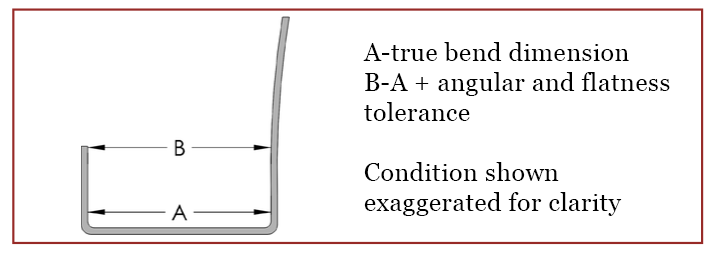
Form dimensions should be measured immediately adjacent to the bend radius in order not to include any angular and flatness discrepancy. See the illustration below.
Feature-to-feature dimensions on formed legs of any length on flexible parts will be assumed to be measured in constrained conditions, holding the part fixed to the prints’ angularity specification. This standard is appropriate for the majority of thin sheet metal parts and results in a functional product. This is always true when the assembled part is, by design, held in constrained condition.
For the most economical production, dimension the part in a single direction wherever possible. Because of the sequential nature of the forming process, and the fact that dimensional variation is introduced at each bend, dimensioning in a single direction parallels the process and helps to control tolerance accumulation.
It is generally recommended that dimensioning be done from a feature to an edge. Feature-to-feature dimensions in two planes should be avoided. Feature-to bend dimensions may require special fixtures or gauging.
This also means that tolerances in the title block of a drawing may be unnecessarily restrictive for certain dimensions and angles, while very appropriate for others.
Download the Red Book!
If you’re interested in reading the full version of the Metalforming Design Handbook, click the button below.