Posted: Jan 31, 2022
In our last blog, we dove into the sixth chapter of the Metalforming Design Handbook, also known as the “Red Book,” which industry leaders recognize as the go-to manual for precision metal forming practices. Chapter Six taught us about punched holes. Now, join us as we take a closer look at extruded holes in Chapter Thirteen!
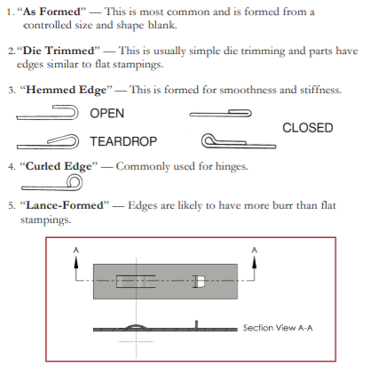
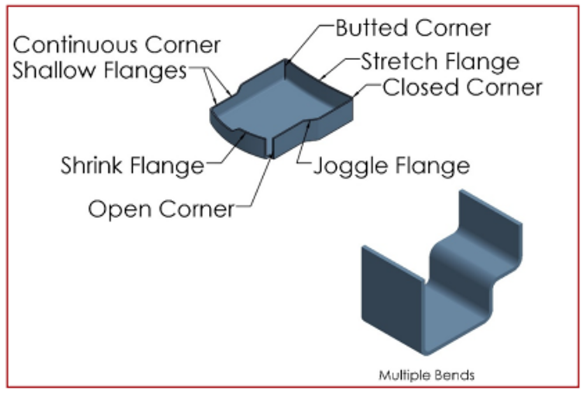
Elements of Formed Stampings
Specifications and Measurement of Formed Parts
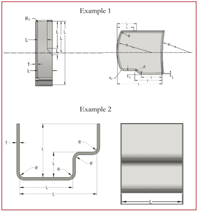
Preferred dimensioning and points to measure:
R2 = Radius in flat blank
See two typical examples below.
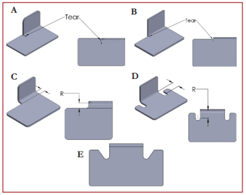
Position of the Form
Diagram “A” illustrates a design that is not desirable for quality or economy. When the form is inside the blank profile, as shown, the material must be torn through the stock thickness and the bend radius. If the part is under stress, this tear will likely cause fatigue failures. In addition, stock tooling cannot be adapted because the flat area adjacent to the form must be held in position during forming, which means extra tooling expense.
Diagram “B” illustrates a similar condition but with the form just outside the blank profile. In this case, the tear extends to the center of the required bend radius.
Diagrams “C” and “D” illustrate a possible solution by changing the blank profile to provide relief for the bend. Besides eliminating the chance of fatigue under stress, there is a possibility of using stock 90-degree vee punches and dies. The results are better quality and less expensive engineering charges.
If the relief notches in illustration “D” are wide enough compared to the material thickness and the shear strength or are designed like the relief in illustration “E”, they can be included in the blanking operation for very little engineering cost and no extra operation.
Height of the Form
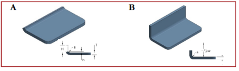
Diagram “A” illustrates a 90-degree bend with insufficient height (H) to form properly.
Consequently, the stock must be added so the form is high enough (H), stock is then cut-off, which means additional tooling and an additional operation.
If (H) is not high enough, the cut-off tool may not have sufficient strength to stand up for a particular material or thickness. This may result in a higher cost secondary operation such as milling.
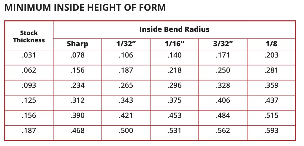
Illustration “B” indicates how to determine the minimum inside height (H), which in this case equals 2-1/2 times the material thickness (T) plus the required bend radius (R).
The concept illustrated by “B” above is converted to chart form below for convenience. These recommended minimum formed height dimensions are general to cover most variables of design, size material types, tempers, and thicknesses. Properly designed small parts and easily formed materials such as aluminum, brass, copper, and mild steel may be formed with a slightly lower minimum inside formed height (roughly 20% less).
Distortion and Interference if Forming
“A” illustrates a distortion condition that occurs in forming. It is a noticeable distortion when a heavy material is bent with a sharp inside bend radius. On material thicknesses less than 1/16, or when the inside forming radius is large in comparison to the material thickness, distortion is barely noticeable.
The material on the inside of the bend is under compression which results in this bulge condition on the edges. In addition, the edges on the outside of the bend are under tension and tend to pull inside.
This bulge or distorted condition is usually of no concern and is accepted as a standard practice unless the bulging will cause any interference with a mating part. This interference should be referred to on the print so a secondary operation can be considered to remove it. The extra operation may not require tooling but it will add to the cost of production.
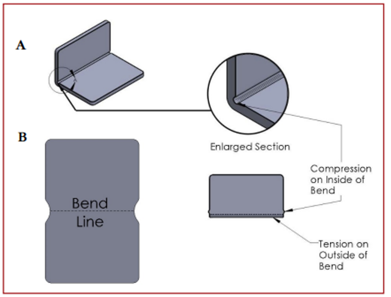
“B” illustrates a blank developed to present interference resulting from the bulge without extra production cost.
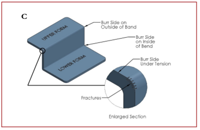
The upper left-hand form (enlarged section) in Illustration “C” indicates a fracture condition that occurs when the burr side of the blank is on the outside of the bend.
This fracture condition occurs because the burr side of the blank on the outside of the bend is under tension and causes the minute fractures on the sharp edge to open and in extreme cases become visible.
Blanks should be produced so the burr side will be on the inside of the bend which is under compression like the lower form. However, when print requirements prevent this, or when a bend is in an opposite direction, like the upper form, fractures may occur.
Tumbling or deburring before forming can minimize the fracture in most cases. On extra heavy material with a very sharp inside bend radius, or on materials difficult to form, like SAE4130, tumbling before forming may not be adequate. It may be necessary to hand file or disc sand a radius on the sharp edges. Such secondary operations will add to the cost of production.
Therefore, for the most economical production and if the design will permit, ample inside bend radii should be permitted for heavy and difficult forming material when the burr side of the blank must be on the outside of the bend.
If slight fractures are permissible, it should be indicated on the print or inquiry.