
Posted: Dec 21, 2021
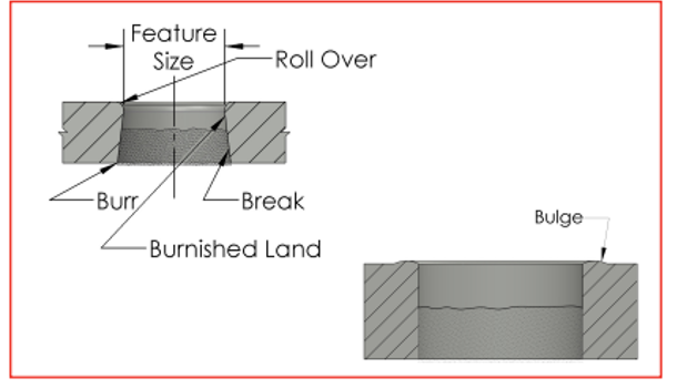
Definition of Punched Holes
Identification of these punched holes can provide the basis for determining the inspection parameters. Roll-over is the natural consequence of the punching process, the mechanical properties of the material being punched, and the die application of techniques employed.
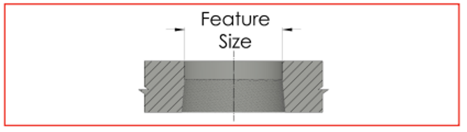
Specification and Measurement of Punched Holes
Special Purpose Holes
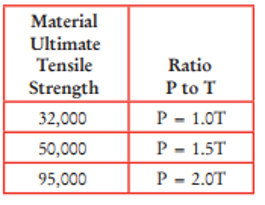
Recommended Minimum Ratios of Punched Hole Diameters to Stock Thickness
Limitations are established in common practice for most economical production. Recommended ratios are applicable to all common metals.
P = Punched Hole Diameter (0.062 min. dia.)
T = Stock Thickness
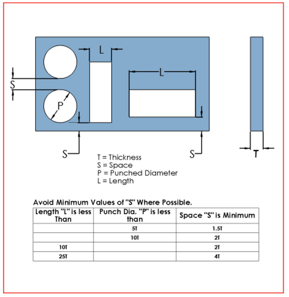
Spacing of Hole Edge to Part Edge and Adjacent Holes
Economical minimum spacing of punched holes to a straight edge or other hole is established. Distortion is not more than 5 percent of metal thickness.
T = Thickness
S = Space
P = Punched Diameter
L = Length
Avoid minimum values of “S” where possible.
Piercing – Adjacent to Bends
Illustration “A” indicates that the minimum inside distance required from the edge of a hole to a bend is 1-1/2 times the material thickness (T) plus the bend radius (R).
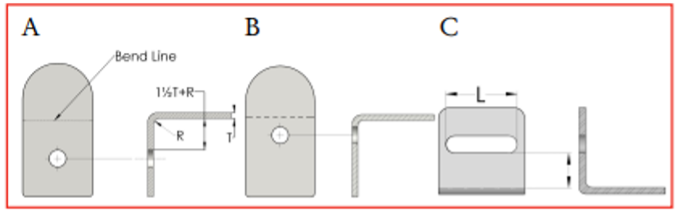
Otherwise, distortion will occur as indicated in Illustration “B” — or piercing after form must be considered.
Illustration “C” indicates a similar condition to “A”, except for openings with an edge parallel to bend. In this case the following requirements apply for economical tooling and production:
When “L” = up to 1 — 2T + R (minimum).
When “L” = 1 to 2 — 2-1/2T + R (minimum).
When “L” = 2 or more — 3T to 3-1/2T+ R (minimum).
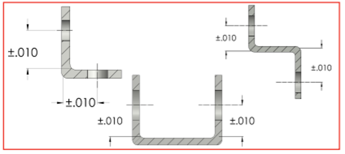
Minimum recommended tolerances are shown below: (on multiple bends each bend is made separately).
Download the Red Book!
If you’re interested in reading the full version of the Metalforming Design Handbook, click the button below.